Barrel Stage Wiring
The barrel stage wiring section of this manual contains descriptions of the individual stage wiring for the barrel portion of the DEIMOS Spectrograph. It corresponds to the Barrel Stage Wiring tab in the electronics schematics binder.
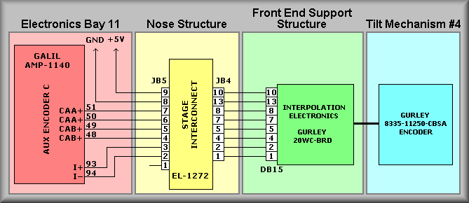
Grating Tilt #4 Stage,
![]() EL-3064
EL-3064
Schematic: schematics/GRTILT4.sch.pdf
Page last updated: January 24, 2003
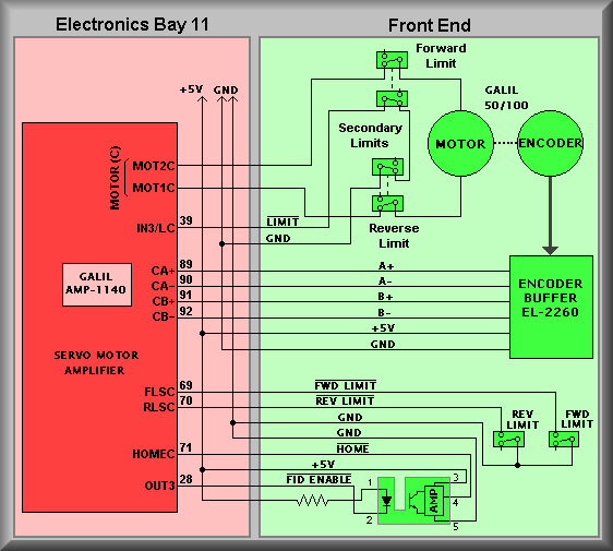
Simplified Drawing
The Grating Tilt #4 stage, though the movement is rotational, is considered a constrained, linear stage. This means that the motor moves the stage between forward and reverse limits. Electronically, this stage consist of the following components:
1. DC servo motor with integral optical disc encoder 2. Slotted optical switch that is used as the fiducial 3. Forward and reverse primary limit switches 4. Forward and reverse secondary limit switches
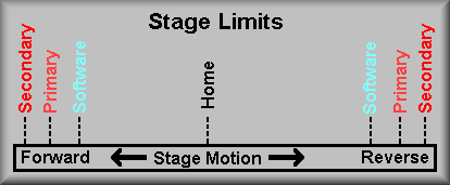
Stage Homing
This stage has the normal compliment of limits. These include, in order, the software limits, the primary limits and the secondary limits. The software limits are set to limit the range of motion of the stage to safe bounds. These limits have been determined empirically. To be enforced, the stage must be homed before initial use of the stage. The next set of limits a moving stage may encounter are the Primary Limits.
Stage Limits
Troubleshooting:
If the TV Focus stage will not move there are several steps to be taken to isolate the problem:
1. Visual Inspection: Remove the appropriate hatch(es) to gain access to the TV camera stage. Looking into the stage check that the pink drive belt hasn't broken or come off of it's pulleys. Look into the limit switch area to determine that the switches and the wiring is intact. Check to see if the limit actuator is positioned within the limits. Finally, with the servo power off, check to see that the lens focus ring rotates freely by manually rotating the ring by moving the drive belt.
2. Cables: The first thing to look at is the cabling. Start at Galil controller panel #1 and check that it's stage cable is connected to J2. (As this stage does not use an auxiliary encoder, there should be no cable connected to J21). Next, look at the EL-1236 interconnect box cables. It is located at the front of the instrument on one of the supports for the front bulkhead. It is labeled TV Focus. (Note: the TV Focus interconnect box is also located in this area.) The main cable comes into the box from the rear part of the instrument and connects to JB1. The connectors leaving the box on the other side are JB2, JB3, and JB6. JB2 is the motor power cable. If it is disconnected the secondary limit signal will float high telling the controller that the stage is in the limit and also there will be no power to the motor. JB3 contains the connections for the primary limits and the fiducial. If it were unplugged you would get a primary limit error, again because with the cable off the controller sees the forward and reverse primary limits as being made (i.e. the input floats high.) The last cable is the ribbon cable that connect the motor encoder to the controller. If this cable was off the controller would try to move the stage. The motor would start to turn but the encoder would not change. Because the software sets the OE (Off on Error) the motor will turn off as soon as it has moved a small way. This is the result of the error in commanded position versus actual position has grown larger then the ER error value.
3. Power Supplies: The next logical place to check is the power supplies.
The supplies in question are the 28V motor power, the 5V, +/-12V logic power,
and finally the power supplies in the Galil controller. First, open the necessary
covers on the electronics ring to gain access to Galil panel #1. The Logic
Supply +5V can be measured across the +5 and GND terminal strips TBA and TBB.
The +28V power supply can be measured across the two large large terminals
on the Lambda power supply. The trickiest to measure is the Logic Supply +/-12V
supplies. To get to the terminals of this supply the supply has to be removed
from the Galil panel. To do this, remove the AC power cord that supplies the
panel (the second power cord on the Panel plugs directly into the Galil controller
and needn't be unplugged). Next, locate and remove the clear plastic AC shield
that protects the AC input terminals of the logic supply. Remove the Allen
head cap screws that attach the Logic Supply to the Opto-22 relay rack support.
Now lay the supply out to where you can get to the +/-12V terminals with a
meter and carefully plug the AC power back in. Measure between the +12V terminal
and any GND terminal on TBB. Do the same for the -12V supply. On the Galil,
extra connectors have been crimped onto the ribbon cables that connect the
controller to the amplifiers. These connectors provide test points for all
of the signals from the controller, including the internal power supply lines.
To measure the Galil power supply insert probes into the following pins
Ground Pin 1 +5 volts Pin 59 +12 volts Pin 57 -12 volts Pin 58
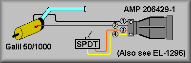
4. Isolate the problem: Use a spare Galil 50/1000 motor to determine if the motor is being servoed. This can be done by connecting a spare motor by using the motor/limit test setup as shown below to the stage interconnect box.
Motor Test Connector
- log onto keamano as kics using the kics password for keamano.
- Type: deimos stop dispatcher2.1
- telnet to Galil #1: telnet 192.168.1.2 2005
- Hit <return> a couple of times until you get the colon prompt :
Step 2: First, issue a MO (Motor Off) from the Galil command line. This will remove power from all motors if it is not already off. Disconnect the motor connector JB2 and the encoder connector JB6 from the stage interconnect box. Connect the Motor Test Connector's JB2 motor connector and JB6 encoder ribbon cable connectors. Now issue a SHB (Servo Here channel B) from the Galil command line. This should servo the motor and you should feel stiff resistance to rotating the shaft. If the motor runs away, remove motor power as above with the MO command, swap the red and black wires at the motor, and servo the motor again. Swapping the motor leads should ensure the motor runs the same direction as the encoder. If the motor runs away again the problem is likely that either 1) the EL-2260 Encoder Buffer has failed, 2) there is a problem in the Interconnect Box, or 3) there is a problem in the stage cable. If this is the case, next try inserting the spare EL-1236 Interconnect Box in place of the original and repeat the above test. If this test fails inspect the cable ends and pins for broken or bent pins. If the test motor servos but the stage motor doesn't, carefully check the wiring from the interconnect box to the motor. If the wiring looks OK, issue the MO command and reconnect the stage cables JB2 and JB6 to the interconnect box. Disconnect the red and black leads from the motor and connect them to the test motor. Issue the SHB command and again test the motor shaft for servo power.
Step 3: If the test motor servos OK test the Secondary limit switch by reading input bit 2 using: MG@IN[2] Change the state of the secondary limit test switch and retest. With the switch in the open position IN[2] should read back as a 1. With the switch closed it should read back as a 0. This will tell you that the secondary limit wiring to the controller is OK.
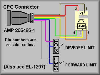
Step 4: If the above steps tell you that the motor and it's wiring are OK then install the Limit Test connector to test the primary limits and the fiducial input. First, set both test switches into the closed positions. Next, issue the command TSB (Tell Switches B axis). This will tell you the state of the primary limits.
Limit Test Connector
Convert the hex number that is returned into binary to check the states of the various limit inputs. Bit 3 will tell you the state of the forward limit switch and bit 2 will tell you the state of the reverse limit switch. Now, change the forward limit test switch and issue the TSB command again. You should see that the value read back has changes by 4. Repeat the test for the reverse switch and see that the returned value now changes by 2.
Step 5: Test the fiducial. First, enter the command: SB2. Now, issue the command TSB. Convert the hex number that is returned into binary to check the state of the HOME input. Bit position 2 should read as a 1. If not, look for short to ground on the HOME signal wire. If it does read as a 1 then issue the command CB3. This turns on the emitter section of the optical slotted switch. With the slot not blocked, issue the TSB command again. This time bit position 2 should read as a 0. If not, look for a short to ground on the HOME signal wiring. Now, block the slotted switch and issue the TBS command again. Bit position 2 should read as a 1 once again.
Step 6: If the stage is still not functioning correctly try isolating the main stage cable by plugging the stage test cable into J2 of Galil controller #1. Plug the other end into the spare EL-1236 Interconnection box. Plug in both the Motor Test connector and the Limit Test connectors into the interconnection box and start back at step 2 above.
Step 7: After replacing any defective components restart the above procedure at step 2.
To exit:<Control> ] (control key and right bracket key)
telnet> quitRestart Dispatcher:deimos start dispatcher2.1