Barrel Stage Wiring
The barrel stage wiring section of this manual contains descriptions
of the individual stage wiring for the barrel portion of the DEIMOS Spectrograph.
It corresponds to the Barrel Stage Wiring tab in the electronics schematics
binder.
Grating Tilt #3 Stage,
 EL-3062
Schematic: schematics/GRTILT3.sch.pdf
Page last updated: March 18, 2003
Simplified Drawing
The Grating Tilt #3 stage, though the movement is rotational, is considered
a constrained, linear stage. This means that the motor moves the stage
between forward and reverse limits. Electronically, this stage consist
of the following components:
| |
1. DC servo motor with integral optical disc encoder |
| |
2. Slotted optical switch that is used as the fiducial |
| |
3. Forward and reverse primary limit switches |
| |
4. Forward and reverse secondary limit switches |
The motor/encoder is from Galil and is the same basic motor
that has been used both in the ESI and HIRES instruments. The Galil part
number is 50-1000. The motor is rated at 30 oz-in (0.21 Nm) of torque, 3750
rpm, and 1000 line encoder. The slotted switch is an OPB970T55 component
from Optek (at one time TRW). The primary limits are SPDT switches from
Microswitch #BZ-2RW822-A2 and the secondary limits are Microswitch #DT-2RV22-A7
DPDT switches. Note: the intervening connectors for the stage have been
left off of the drawing for clarity. The complete schematic can be viewed
by clicking the schematic button above.
The stage is driven by software commands sent to it's controller.
The controller then uses software supplied parameters to generate an analog
voltage in the range of -10V to +10V that goes to the power amplifier. The
amplifier then drives the motor. The control loop is closed via the integral
motor encoder.
Using this scheme, the control computer will issue a command
such as PAB=1000 (
Position
Absolute axis B to encoder position
1000). The controller interprets the command and using preprogrammed acceleration,
deceleration, and speed parameters, it determines the analog voltage output
needed to move the motor to the correct position. This includes calculating
the proper time to start decelerating the motor to come to a stop at the
desired point. (There are many other set parameters burnt into the Galil
controller such as feedback parameters, torque limits and the like). The
derived analog output voltage is then applied to the power amplifier. The
amplifier performs two functions. First, the amplifier provides an output
current proportional to the input voltage. This is a conversion of one volt
to one ampere. Second, it provides a pulse width modulated output to drive
the motor. This signal is present whenever the AEN (
Amplifier
ENable)
is asserted (TTL High). The AEN signal goes high when the SH (
Servo
Here) command is issued and goes low when either the MO (
Motor
Off) command is issued, or, if the OE (
Off on
Error)
variable is set true, when the position error is greater then the error
limit ER. The encoder supplies A and B phases in quadrature and thus is
decoded to 4000 counts per revolution.
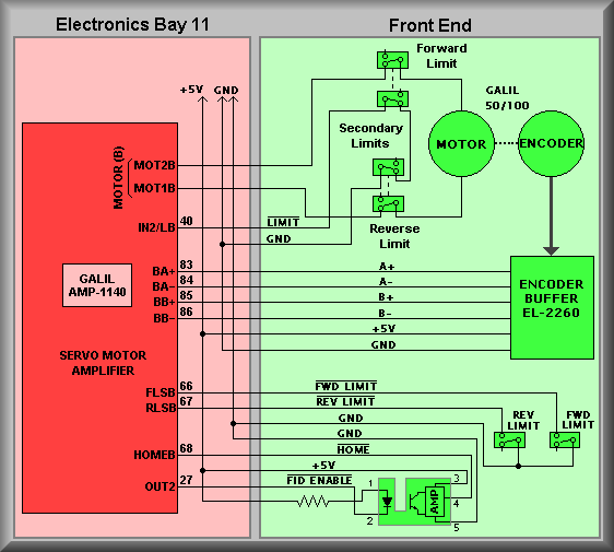
Grating Tilt 3 is connected to channel B of controller #2 via the Galil
AMP-1140 module. The connections shown on the amplifier module refer to
the screw terminals thereon. For instance, the encoder output connections
are made to screw terminals 83-86. The signal names on the amplifier module
reflect the A+ and A-, and the B+ and B- phases of the encoder. The second
letter, B, refers to the controller channel to which the signals are connected.
At the right-hand side of the drawing is the
EL-2260
Encoder Buffer board. This board converts the unipolar encoder outputs
to differential signals and drives the encoder cable. At the bottom of the
amplifier block are the connections to the HOME fiducial. The signal
OUT2
is used to enable the slotted optical switch, or the fiducial. A clear bit
instruction,
CB2, pulls the output line low causing the emitter section
of the fiducial to turn on which illuminates the receiver portion of the
switch. With this done, the stage can be moved to find the edge of a blade
that is attached to the stage
Simplified Drawing
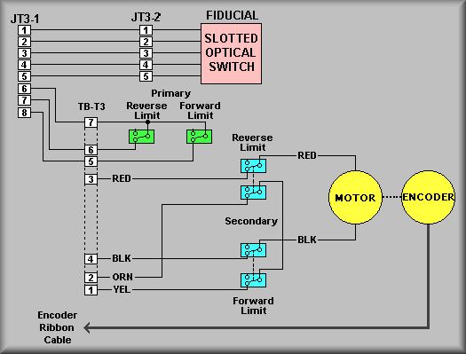
The above and below drawings show the details of the wiring of
Grating Tilt #3 on the 'slider' stage. Above is the schematic and below is a
pictorial view of the wiring. The wiring from these views
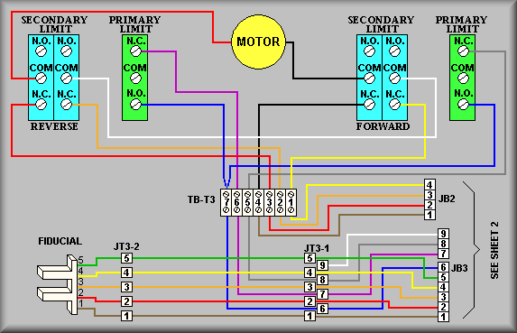
Simplified Drawing
Simplified Drawing
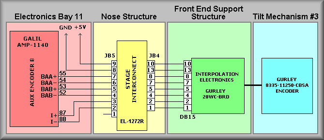
The above drawing shows the interconnection of the Gurley Precision high resolution
encoder. In the blue box, the encoder resolution is 11,250 counts per revolution
in quadurature. The green box shows the Gurley Interpolation amplifier. The
interpolator increases the number of counts by 20. This gives a final resolution
of 900,000 (11250 X 4 X 20) counts per revolution. Following the signal path,
the output of the interpolation amplifier is cabled to the Grating Stage #3
interconnect box (in yellow). From the interconnect box the signals flow to
the auxiliary encoder inputs for the B axis. Note that the Gurley index signal
is wired into the normal axis index input. Because the motor encoder is zeroed
via the homeing procedure it's index input is not used. This leaves it freed
up for the much higher resolution Gurley Precision encoder. The

Stage Homing
Because the blade is made to cover the slotted switch
for one half of the stages rotation, the software can determine which
direction to move the stage to get to the correct edge of the blade to
'zero out' the stage. For example, if the fiducial is turned on and the
HOME signal is high, then the fiducial beam is blocked and the software
knows which half of the stage it is in. On the other hand, if the fiducial
is turned on and the HOME input is high the software knows it is in the
other half. By knowing which half the stage is in the software knows which
direction to go to find the proper edge of the blade and thus set the
zero point for the stage. The homing routine consists of running the stage
at a normal speed until it sees a transition of the HOME signal then it
moves the stage a short distance to position itself on the correct side
of the blade and finally, it moves at a very slow speed until it sees
the HOME signal change state. By executing it's homing routine, the software
can set the stage to it's zero point. Subsequently, it can set to any
of the filters positions since they are a fixed distance from the HOME
point. The fixed positions for the stage can be found on the TV Focus
Stage Data Sheet. As indicated on the drawing, Ground and +5 volts are
supplied to both the encoder and the fiducial.
This stage has the normal compliment of limits. These include,
in order, the software limits, the primary limits and the secondary limits.
The software limits are set to limit the range of motion of the stage to safe
bounds. These limits have been determined empirically. To be enforced, the stage
must be homed before initial use of the stage. The next set of limits a moving
stage may encounter are the Primary Limits.
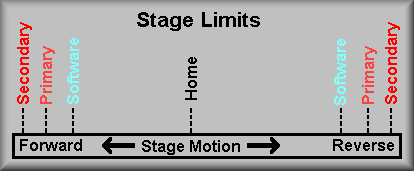
Stage Limits
These are shown on the drawing as the FLSA ( Forward
Limit Switch channel A) and the RLSA ( Reverse Limit
Switch channel A). Their function is to stop the motion of the
stage if they are activated. These are inputs to the motion controller that
causes the controller to stop any further movement in that direction. It will,
however, allow you to move back out of that limit. Notice that to get to these
limits the stage has already violated the software limits. The secondary limits
are there to prevent physical harm to the stage. These limits are DPDT switches
that perform two functions. First, one pole of the switch is wired in series
with one pole of the motor. When the switch is activated the power to the motor
is cut off. THIS MEANS THAT THE STAGE MUST BE DRIVEN OUT OF THESE LIMITS BY
HAND. At this point, the stage requires manual intervention for the safety
of the stage. The second set of contacts are wired to supply a signal to the
controller that the limit has been tripped. This signal is fed to the controller
input IN2 on pin 40 of the amplifier terminal strip. Because the forward and
reverse switches are wired in series, this input does not contain information
as to which direction the stage was traveling, just that it is in a secondary
limit. Again notice, to get to this limit both the software and primary limits
have failed. Though the simplified drawing above does not show the stage interconnect
box, the schematic does. It is important to note that the connectors to the
interconnect box must all be plugged in to operate the stage. The limits are
all wire via Normally Closed terminals on the switches. If a cable is disconnected
the controller recognize the limit inputs as being active thus not allowing
that stage to move.
If the TV Focus stage will not move there are several steps to be taken to
isolate the problem:
1. Visual Inspection: Remove the appropriate hatch(es) to gain access
to the TV camera stage. Looking into the stage check that the pink drive belt
hasn't broken or come off of it's pulleys. Look into the limit switch area
to determine that the switches and the wiring is intact. Check to see if the
limit actuator is positioned within the limits. Finally, with the servo power
off, check to see that the lens focus ring rotates freely by manually rotating
the ring by moving the drive belt.
2. Cables: The first thing to look at is the cabling. Start at Galil
controller panel #1 and check that it's stage cable is connected to J2. (As
this stage does not use an auxiliary encoder, there should be no cable connected
to J21). Next, look at the EL-1236 interconnect box cables. It is located
at the front of the instrument on one of the supports for the front bulkhead.
It is labeled TV Focus. (Note: the TV Focus interconnect box is also located
in this area.) The main cable comes into the box from the rear part of the
instrument and connects to JB1. The connectors leaving the box on the other
side are JB2, JB3, and JB6. JB2 is the motor power cable. If it is disconnected
the secondary limit signal will float high telling the controller that the
stage is in the limit and also there will be no power to the motor. JB3 contains
the connections for the primary limits and the fiducial. If it were unplugged
you would get a primary limit error, again because with the cable off the
controller sees the forward and reverse primary limits as being made (i.e.
the input floats high.) The last cable is the ribbon cable that connect the
motor encoder to the controller. If this cable was off the controller would
try to move the stage. The motor would start to turn but the encoder would
not change. Because the software sets the OE (Off on Error)
the motor will turn off as soon as it has moved a small way. This is the result
of the error in commanded position versus actual position has grown larger
then the ER error value.
3. Power Supplies: The next logical place to check is
the power supplies. The supplies in question are the 28V motor power, the 5V,
+/-12V logic power, and finally the power supplies in the Galil controller.
First, open the necessary covers on the electronics ring to gain access to Galil
panel #1. The Logic Supply +5V can be measured across the +5 and GND terminal
strips TBA and TBB. The +28V power supply can be measured across the two large
large terminals on the Lambda power supply. The trickiest to measure is the
Logic Supply +/-12V supplies. To get to the terminals of this supply the supply
has to be removed from the Galil panel. To do this, remove the AC power cord
that supplies the panel (the second power cord on the Panel plugs directly into
the Galil controller and needn't be unplugged). Next, locate and remove the
clear plastic AC shield that protects the AC input terminals of the logic supply.
Remove the Allen head cap screws that attach the Logic Supply to the Opto-22
relay rack support. Now lay the supply out to where you can get to the +/-12V
terminals with a meter and carefully plug the AC power back in. Measure between
the +12V terminal and any GND terminal on TBB. Do the same for the -12V supply.
On the Galil, extra connectors have been crimped onto the ribbon cables that
connect the controller to the amplifiers. These connectors provide test points
for all of the signals from the controller, including the internal power supply
lines. To measure the Galil power supply insert probes into the following pins
| |
Ground |
Pin 1 |
| |
+5 volts |
Pin 59 |
| |
+12 volts |
Pin 57 |
| |
-12 volts |
Pin 58 |
4. Isolate the problem: Use a spare Galil 50/1000 motor to determine
if the motor is being servoed. This can be done by connecting a spare motor
by using the motor/limit test setup as shown below to the stage interconnect
box.
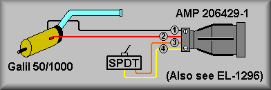
Motor Test Connector
Step 1: Stop dispatcher #1 and login to Galil controller
#1:
-
log onto keamano as kics using the kics password
for keamano.
-
Type: deimos stop dispatcher2.1
-
telnet to Galil #1: telnet 192.168.1.2 2005
-
Hit <return> a couple of times until you get
the colon prompt :
Step 2: First, issue a MO (Motor Off) from the Galil
command line. This will remove power from all motors if it is not already
off. Disconnect the motor connector JB2 and the encoder connector JB6 from
the stage interconnect box. Connect the Motor Test Connector's JB2 motor connector
and JB6 encoder ribbon cable connectors. Now issue a SHB (Servo Here
channel B) from the Galil command line. This should servo the motor
and you should feel stiff resistance to rotating the shaft. If the motor runs
away, remove motor power as above with the MO command, swap the red and black
wires at the motor, and servo the motor again. Swapping the motor leads should
ensure the motor runs the same direction as the encoder. If the motor runs
away again the problem is likely that either 1) the EL-2260 Encoder Buffer
has failed, 2) there is a problem in the Interconnect Box, or 3) there is
a problem in the stage cable. If this is the case, next try inserting the
spare EL-1236 Interconnect Box in place of the original and repeat the above
test. If this test fails inspect the cable ends and pins for broken or bent
pins. If the test motor servos but the stage motor doesn't, carefully check
the wiring from the interconnect box to the motor. If the wiring looks OK,
issue the MO command and reconnect the stage cables JB2 and JB6 to the interconnect
box. Disconnect the red and black leads from the motor and connect them to
the test motor. Issue the SHB command and again test the motor shaft for servo
power.
Step 3: If the test motor servos OK test the Secondary
limit switch by reading input bit 2 using: MG@IN[2] Change the state of the
secondary limit test switch and retest. With the switch in the open position
IN[2] should read back as a 1. With the switch closed it should read back as
a 0. This will tell you that the secondary limit wiring to the controller is
OK.
Step 4: If the above steps tell you that the motor and it's
wiring are OK then install the Limit Test connector to test the primary limits
and the fiducial input. First, set both test switches into the closed positions.
Next, issue the command TSB (Tell Switches B axis). This
will tell you the state of the primary limits.
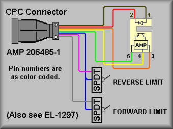
Limit Test Connector
Convert the hex number that is returned into binary to check the states
of the various limit inputs. Bit 3 will tell you the state of the forward
limit switch and bit 2 will tell you the state of the reverse limit
switch. Now, change the forward limit test switch and issue the TSB
command again. You should see that the value read back has changes by
4. Repeat the test for the reverse switch and see that the returned
value now changes by 2.
Step 5: Test the fiducial. First, enter the command: SB2. Now,
issue the command TSB. Convert the hex number that is returned into
binary to check the state of the HOME input. Bit position 2 should read
as a 1. If not, look for short to ground on the HOME signal wire. If
it does read as a 1 then issue the command CB2. This turns on the emitter
section of the optical slotted switch. With the slot not blocked, issue
the TSB command again. This time bit position 2 should read as a 0.
If not, look for a short to ground on the HOME signal wiring. Now, block
the slotted switch and issue the TBS command again. Bit position 2 should
read as a 1 once again.
Step 6: If the stage is still not functioning correctly try
isolating the main stage cable by plugging the stage test cable into
J2 of Galil controller #1. Plug the other end into the spare EL-1236
Interconnection box. Plug in both the Motor Test connector and the Limit
Test connectors into the interconnection box and start back at step
2 above.
Step 7: After replacing any defective components restart the
above procedure at step 2.
Step 8: Logout and restart the dispatcher:
<Control> ] (control key and right
bracket key)
telnet> quit
deimos start dispatcher2.1