Barrel Electronics
The barrel electronics section of this manual contains descriptions
of the barrel electronics for the DEIMOS Spectrograph. It corresponds to the
Barrel Electronics tab in the electronics schematics binder.
Ion
Pump Monitor Wiring,  EL-3014
Schematic: schematics/IONWIRE.sch.pdf
Page last updated: June 20, 2002
(Click on image for larger view)
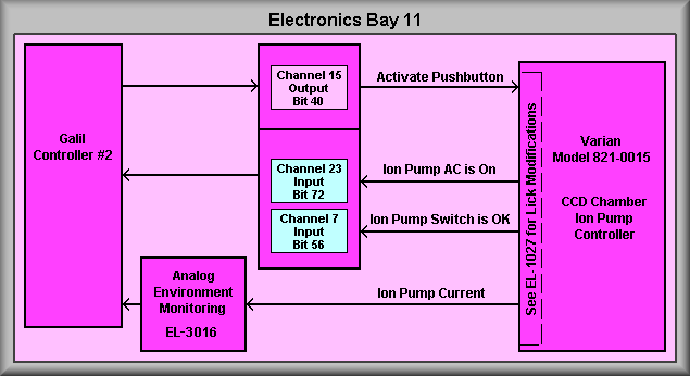
This schematic shows the wiring that is in place to allow the
control computer to monitor the state of the ion pump controllers. This includes
reading the ion pump current, reading the state of the front panel rotary switch,
and remotely activate the start pushbutton. The two sheets of this schematic
show the connections for the CCD chamber, sheet 1, and the N2 vessel, sheet
2. In that both sheets are identical only sheet 1 will be described.
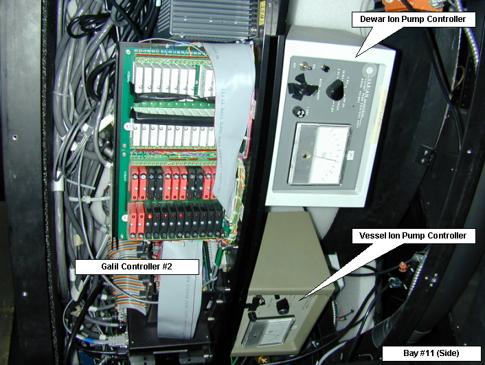
To the left of the page is Galil controller #2. The ion pump
controllers are connected to the controller via the expansion I/O (center of
diagram) and it's analog inputs via the Analog input card (lower left). The
Varian Ion Pump Controllers (right side of drawing) have been modified by UCO/Lick
for remote operation. This is accomplished by 1) detecting the current flow
to the ion pump, 2) supplying an analog voltage output that is proportional
to the current, 3) supplying an input that can mimic the action of pushing the
reset button, and 4) sending back the state of the controller's AC as seen after
the intervening shut down relay. The modifications, in essences, shut down the
AC power to the controller if the current raises above a safe level of about
50 ma. Large currents, that may occur if the dewar warms up, could damage the
actual ion pump. For more details on the UCO/Lick modifications, see
EL-1027
in the
Miscellaneous Drawings section of this manual. Also, the rotary
switch that selects the current range for the controller's front panel meter
has been modified to close a set of contacts when the switch is in the correct
position.
For the chamber controller, the Galil monitors the AC power via input channel
22, bit 71, of Opto-22 panel #5. The current select switch input is monitored
via channel 6, bit 55. The remote activation of the 'reset' pushbutton is
handled by output channel 14, bit 39, of Opto-22 panel #4. The final function
is the monitoring of the ion pump current. The signal from the ion pump controller
is applied to input 2A of the Analog Input Card attached to Galil controller
#2. See the page on the Analog Input
card for more details on working with this card.
Chamber Ion Pump Controller

Vessel Ion Pump Controller