Barrel Electronics
The barrel electronics section of this manual contains descriptions
of the barrel electronics for the DEIMOS Spectrograph. It corresponds to the
Barrel Electronics tab in the electronics schematics binder.
Overall
Block Diagram,
 EL-3001
Schematic:
schematics/SERVO.sch.pdf
Page last updated: June 17, 2003
Jump to: Sheet 2, sheet 3
This
3 sheet schematic gives a general overview of the control electronics on the
rotating portion of the DEIMOS instrument. (The Cradle
Electronics section of this manual gives the same kind of information
for the non-rotating part of the instrument.) The first sheet shows the overall
interconnections and communications between the various components of the
system. Sheet 2 illustrates the expansion I/O connections for Galil Controller
#1 and sheet 3 illustrates the expansion I/O connections for Galil Controller
#2.
Sheet 1:
Simplified Drawing
Photos
|
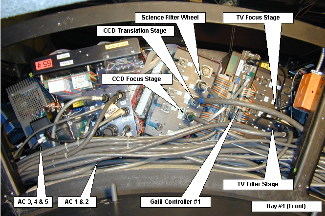
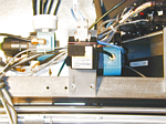
Galil panel #1
|
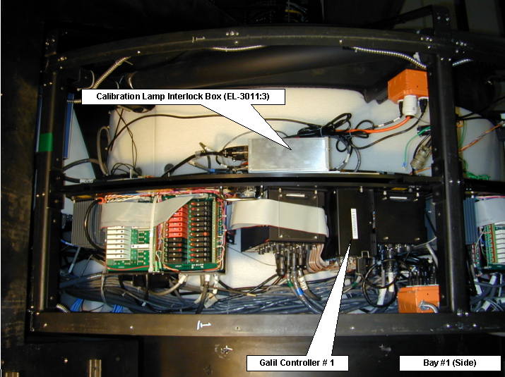
Galil panel #1 and Lamp interlock box
|
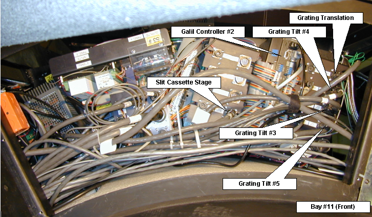
Galil panel #2
|
Galil panel #2 and Ion Pump controllers
|
|
|
|
|
|
|
|
|
|
|
|
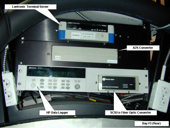
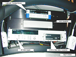
Lantronix, A2S convertor, Data Logger, and SCSI-to-Fiber
convertor
|
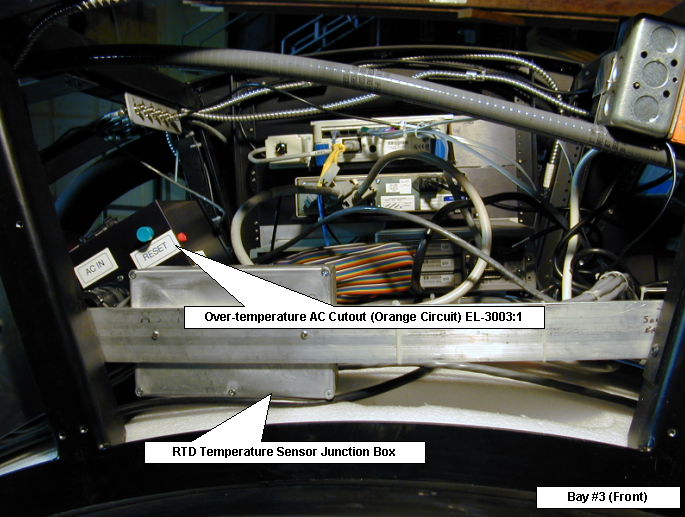
Orange circuit over temperature control and HP data
logger sensor junction box
|
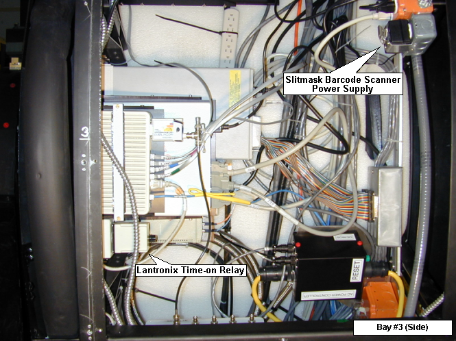
Lantronix Time-on Relay and Slitmask Barcode Supply
|
|
|
|
|
|
|
|
|
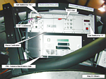
Lantronix Terminal Server: (see Bay
3 photo)
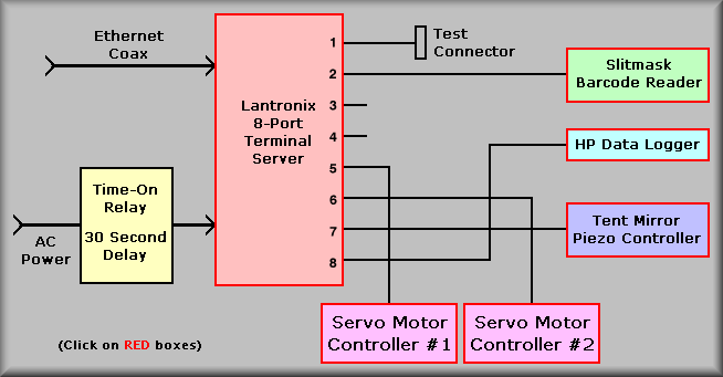
This sheet shows all of the components of the electronics mounted in the electronics
ring except the CCD controllers. At the top of the drawing are the communication
lines of the instrument. The block in the top left represents the Lantronix
ETS8P terminal server. The terminal server supplies 8 serial port using RJ-45
connectors. The ports are allocated as follows:
- Test port - left open for direct connection to the Lantronix for configuration.
- Slitmask bar code scanner.
- <Not assigned>
- <Not assigned>
- Galil controller #1
- Galil controller #2
- Piezo controller. (Tent Mirror control)
- HP Data Logger. (Temperature logging)
A race condition can exist when power is applied to the instrument. The Lantronix
box can become confused if it receives 'garbage' characters on it's serial ports
while it is powering up. To insure that the Lantronix power is the last box
to come on, a Potter & Brumfield 1.8 to 180 second 'Time-On' delay relay
is wired in series with the AC power for the box. The relay and socket are located
on the back of the Lantronix mounting plate and the delay is set to about 60
seconds.
(Back to Top)
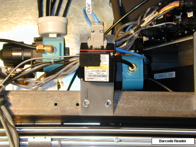
Bar Code Scanner:
Slitmask Barcode Reader
To the right of the Lantronix box are boxes that represent the bar code reader,
the data logger, and the piezo controller. The Symbol Technologies LS 1220 bar
code reader for the slitmask system is mounted inside the instrument on a solid
mount that allows it to scan the bar-codes affixed to the individual slitmasks.
This unit is powered by an AC wall adapter that is located at the back of the
rack containing the Lantronix box. The adapter is held in place with a with
metal strap. Though the power is always on, the beam is
turned off and on via software and currently is planned only to be on when the
slitmasks are initially inserted into the cassette. The scanner is a serial
device and is connected to Lantronix port 2.
(Back to Top)
HP Data Logger: (see Bay
3 photo)
Extra info: 
HP Data logger
Beneath the barcode scanner is the HP
Model 34970A Data Logger. This box can control as many as 30 RTD type sensors
(R.T.D. Company, RS2P-463). The DEIMOS instrument has 27 sensors wired in. The
data is read once every ten minutes and archived on the data
taking computer. The idea is to keep record of the temperatures at various
points on the structure that can be examined to see how the instrument acclimates
to the mountain top and also as a record in case of any unexpected behavior
of the instrument. At this time, there are no plans to display the inputs but
a process can be set up to dump the data to a window if necessary.
(Back to Top)
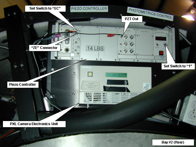
The Physik Instrumente P-845 Piezo Controller:
Piezo Controller
The Piezo control box is again a serial device and it communicates via Lantronix
port 7. It controls the position of the tent mirror which is part of the flexure
compensation system. The tent mirror can steer the light beam to keep the image
on the detector steady as the instrument rotates and flexes. The
actuator is a self contained unit that consists of a piezo element and a strain
gauge. It has a stroke of 90 microns and
can be controlled either via the communications port or front panel controls.
The unit must always be set for remote operation. The operation manual
and user guide accompany the outside vendor manuals bundle.
Front panel
switch settings
PDF version of Operating
Manual
Please note: the controller box
MUST be powered down before connecting or disconnecting the actuator.
(Back to Top)
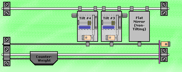
Galil Controller #1:
Extra info:
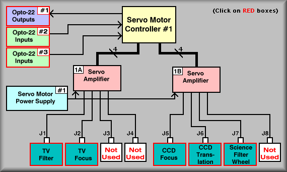
Simplified Drawing - Click on boxes for detailed description
To bring up the detailed description of any stage click on it's box in the
above diagram.
The above drawing illustrates the stages controlled by Galil controller number
1. The yellow block at the top, center of the diagram represents the Galil DMC-1580-72
Servo Motor Controller. The part number indicates that the unit is a 1500 series,
8-axis controller with an additional 72-bit I/O expansion box. To the right
of the controller block are the three I/O racks and below it are two Galil AMP-1140
servo amplifiers. Below the controller are the two AMP-1140 servo amplifiers.
The controller connects via three 50-pin ribbon cables directly to the Expansion
I/O. The expansion I/O consists of three banks of 24 bits. The first 24 bits
can be programmed to be either outputs or inputs. The other two banks are dedicated
as inputs. For our implementation, the first 24 bits are programmed as outputs.
This is done by setting the Galil variable CO to 7. Each bank of 24 bits leave
the Galil controller via a 50-pin ribbon cable. Galil has configured the I/O
pin assignments to match the Opto-22™ G4PB24 I/O rack. We have used these
components to simplify wiring of the instrument.
Below the yellow block are the two pink blocks
that represent the two Amp-1140's. Each amplifier can independently power up
to four servo motors. In the case of amplifier #1A, only two stages are connected:
the TV Filter stage at J1 and the TV Focus stage at J2. These stages are mounted
in the front of the instrument with the Photronics PXL camera. The filter wheel
has eight positions and is normally loaded with 7 filters and an open position.
The TV Focus stage motorizes the focus ring on the Kodak 200 mm lens.
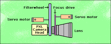
The Filterwheel Stage is an unconstrained stage, meaning that it does not have
forward or reverse limits. The stage is set by finding the fiducial to set the
zero point. The Focus Stage is a standard, constrained stage. It again uses
a fiducial for setting the zero point but also has three types of end of travel
limits: first is the software limit, then the primary hardware limit, and lastly,
the secondary hardware. The software should keep the stage from traveling past
the software limit. If it fails to stop the stage, the primary hardware limit
sends a limit tripped signal to the controller which should stop the motor.
Once the primary limit is violated the controller should only allow the stage
to move away from the limit. If both the software and primary limits fail, the
secondary limit interrupts the power to the motor. At this point, the stage
must be driven out of the limit by physically turning the motor shaft. See the
TV Filter and Focus
pages for more info on these stages.
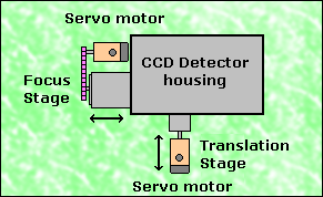
Amplifier 1B controls the CCD dewar focus and
translation stages along with the science filterwheel. Control of the two CCD
stages is unique in the instrument. Due to the small motion of these stages,
the limit switches that had to be used do not come in a 2PDT. Thus, the secondary
limits do not generate a input for the Galil controller. The stages both have
the usual software limits that should keep the stage from reaching the hardware
limits. They also have the primary hardware limit that tells the Galil controller
to stop motion (only) in that direction. The secondary limits, however,
are SPDT switches that are wired in series with the motor current. The difference
with these stages is that the controller does not receive the feedback that
it would get from a normal secondary limit. This is not critical in that the
stages would have to be backed out of the limit manually anyway.
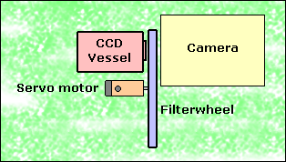
The final stage on controller #1 is the Science Filterwheel
Stage. It is an unconstrained stage, meaning that it does not have forward or
reverse limits. The stage is set by finding the fiducial to set the zero point.
The filters are centered in the beam by moving a predetermined number of encoder
counts.
Galil Controller #2:
Extra info:
Simplified Drawing
The above drawing illustrates the stages controlled by Galil controller number
2. The yellow block at the top, center of the diagram represents the Galil DMC-1580-72
Servo Motor Controller. The part number indicates that the unit is a 1500 series,
8-axis controller with an additional 72-bit I/O expansion box. To the right
of the controller block are the three I/O racks and below it are two Galil AMP-1140
servo amplifiers. Below the controller are the two AMP-1140 servo amplifiers.
The controller connects via three 50-pin ribbon cables directly to the Expansion
I/O. The expansion I/O consists of three banks of 24 bits. The first 24 bits
can be programmed to be either outputs or inputs. The other two banks are dedicated
as inputs. For our implementation, the first 24 bits are programmed as outputs.
This is done by setting the Galil variable CO to 7. Each bank of 24 bits leave
the Galil controller via a 50-pin ribbon cable. Galil has configured the I/O
pin assignments to match the Opto-22™ G4PB24 I/O rack. We have used these
components to simplify wiring of the instrument.
Below the yellow block are the two pink blocks
that represent the two Amp-1140's. Each amplifier can independently power
up
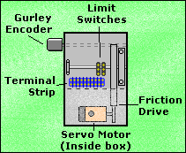
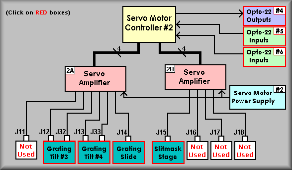
to four servo motors. Amplifier #2A has the following stages connected: J12
and J32 are connected to Grating Tilt mechanism #3, J13 and J33 connect to
Grating
Tilt mechanism #4, and J14 connects to the grating select stage. Connectors
J32 and J33 connect to each stage's auxiliary encoder (Gurley Precision model
8335-11250-CBSA). The secondary encoders are used to position the stage while
the primary encoders are used to close the servo loop. These stages are wired
as normal constrained stages with the addition of the auxiliary encoders. Again,
the constrained stage has software, hardware primary, and hardware secondary
limits. The software limit should stop the tilting motion of the grating when
encountered, the primary limit connects to the Galil controller limits that
should stop any additional motion in the direction of the limit, and the secondary
limit removes power to the motor in case both other limits fail.
|
|
|
|
Grating Tilter #3
|
Grating Tilter #4
|
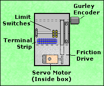
The Grating Select stage is a normal constrained
stage as above. This stage moves the select grating tilt mechanism into the
light path at the grating box. Once there, a set of 5 pneumatic clamps lock
the grating into place. In addition to the normal stage limits and home
fiducial, the grating select stage uses an extra optical-slotted switch (PRM)
to define the position of the selected grating. Under software control, the
select mechanism moves the grating tilt mechanism into rough position for clamping.
Once there, the PRM is activated and the select stage does a homing routine
to the edge of a blocking flag attached to the grating cell. Once that is done
the clamps are activated in a sequence that helps make the final clamping position
as accurate as possible.
Grating Select Stage
Amplifier #2B controls only the Slitmask stage via J15.
The Slitmask stage is really a combination of a constrained motor stage and
a highly specialize pneumatic stage. The servo motor runs what amounts to a
scissors jack that positions the slitmask cassette to discrete positions for
each of the slitmask slots. Again, the constrained stage has software, hardware
primary, and hardware secondary limits; the software limit should stop the scissoring
motion of the stage when encountered, the primary limit connects to the Galil
controller limits that should stop any additional motion in the direction of
the limit, and the secondary limit removes power to the motor in case both other
limits fail.
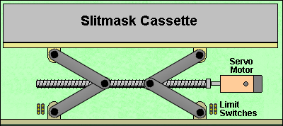
Slitmask Scissors Stage
Sheet 2:
Simplified Drawing
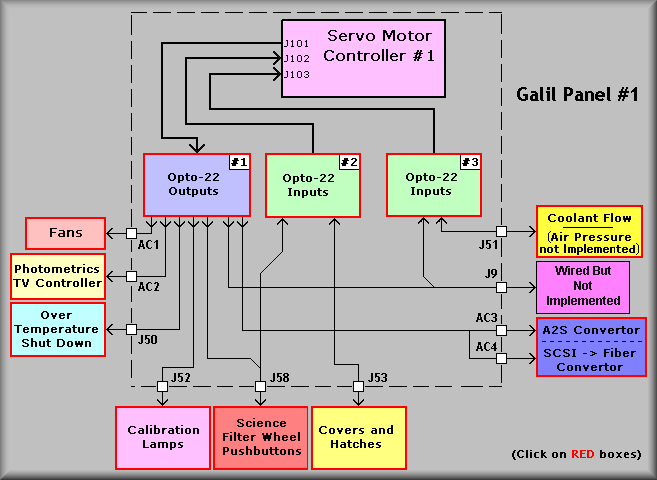
Galil Controller #1 Expansion I/O:
The above drawing shows the connections and cabling for the expansion I/O for
Galil Controller #1. Note that the first I/O block is set for outputs and that
blocks 2 and 3 are inputs. The pinouts for the Galil cables are :
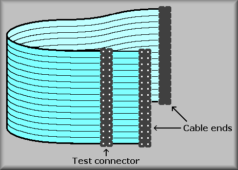
Also note, each of the Galil I/O cables has been fitted with
a spare IDC connector located near the controller end of the cable. This provides
a convenient place to probe the I/O signals when troubleshooting.
Connectors are shown at the edge of the dashed line that represents the controller
panel. These connectors allow the controller panel to be removed and reconnected
by merely disconnecting the I/O, stage cables, communication, and power cables.
The AC1 through AC4 connectors are AC outlets. Their power is controlled via
Opto22 AC output relays.
AC1 is controlled by software and connects to the cooling
fans. The software monitors the temperature within the electronics ring via
a solid-state sensor and uses the fans to keep the temperature within the
ring at about 40° F.
AC2, AC3, and AC4 are used to control the sequence in
which the guide TV camera powers up. To get the camera system to come up reliably,
the power should be turned on in the following sequence:
-
Fiber-to-SCSI convertor
-
AIA-to-SCSI convertor
-
Camera controller
Connector J50 is wired to the EL-3003 AC power controller. This connection
allow the Galil controller software shut down the orange circuit power if the
temperature become too hot. The controller's signal is wired in parallel with
a 85° F thermostat that will force the AC power off if for some reason the
Galil becomes disabled. A quick note: if the thermostat has a lot of histerysis,
if it does trip off the AC, the thermostat will have to cool down before it
will let the power be reapplied.
Connector J52 is the main control cable for the calibration lamp system.
It contains the AC lines that are used to apply power to the various lamp power
supplies.
Connector J58 is the cable for the Filter Wheel pushbutton Station. The
pushbutton station provides local control at the filterwheel for use when loading/unloading
filters.
Connector J53 connects to the hatches that give access to the inside
of the barrel. These are the Man Hatch, Dewar Hatch #1, and Dewar Hatch #2.
The wiring allows the control computer identify which hatch is causing the instrument
to not rotate.
Connector J51 is wired to the Potheus Flow meter. The Photometrics TV
system is powered only when the coolant is flowing.
Simplified Drawing
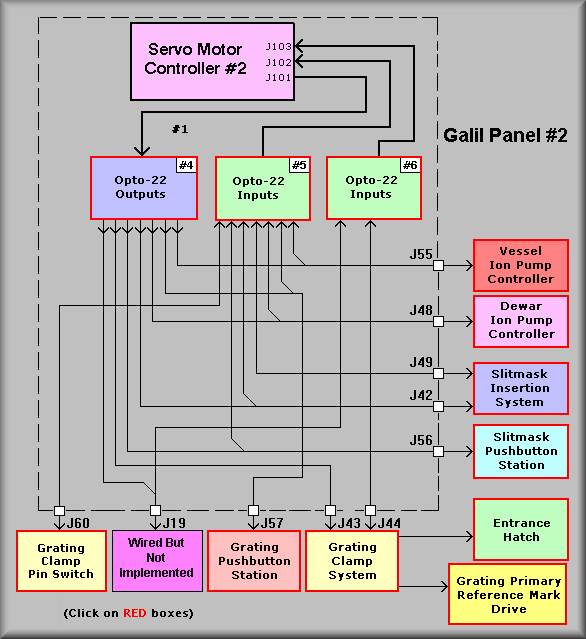
Galil Controller #2 Expansion I/O:
The above drawing shows the connections and cabling for the expansion I/O for
Galil Controller #1. Note that the first I/O block is set for outputs and that
blocks 2 and 3 are inputs. The pinouts for the Galil cables are :
Also note, each of the Galil I/O cables has been fitted with
a spare IDC connector located near the controller end of the cable. This provides
a convenient place to probe the I/O signals when troubleshooting.
Connectors are shown at the edge of the dashed line that represents the controller
panel. These connectors allow the controller panel to be removed and reconnected
by merely disconnecting the I/O, stage cables, communication, and power cables.
The AC1 through AC4 connectors are AC outlets. Their power is controlled via
Opto22 AC output relays.
Connector J60 is wired to the Grating Clamp Pin switch.
The pin is actuated by grating clamp #2. As it clamps, the pin is pushed into
the switch which tells the software that the grating is properly clamped.
Connector J57 is the cable for the Grating Pushbutton Station. The
pushbutton station provides local control at the grating select stage for
use when loading/unloading gratings.
Connector J43 is wired to the grating clamp solenoids. It provides
the signals to activate/deactivate the grating clamps. The grating clamp system
is a series of four clamps, numbered 1, 2, 4, 5, (solenoid 5 actually controls
2 clamps) that push the selected grating slider into position on the grating
box. The entrance hatch solenoid is also located on the grating solenoid panel
and is wired via J43. Lastly, the signal that powers the grating system Primary
Reference Mark sensor is wired through this cable to the solenoid panel where
it branches off to the PRM.
Connector J44 is the grating clamp and entrance hatch cylinder limit
switch cable. Each of the five clamp and two hatch cylinders have magnetic
reed limit switches at both ends of travel. These signals provide feedback
to the control electronics of the actual position of each of the cylindars.
Connector J55 is wired to the CCD coolant vessel Ion Pump Controller.
The cable provides remote operation of the controller by providing an output
that effectively closes the start switch on the controller, and a AC power
on input, a front panel selector switch monitoring input, and an analog input
to read the ion pump current.
Connector J59 is wired to the CCD Dewar 'Chamber" Ion Pump Controller.
The cable provides remote operation of the controller by providing an output
that effectively closes the start switch on the controller, and a AC power
on input, a front panel selector switch monitoring input, and an analog input
to read the ion pump current.
Connector J49 is wired to the Slitmask stage. It contains all of the
monitoring signal associated with the insertion and removal of the slitmasks.
It does not, however, contain the scissors stage wiring. That is wired via
the stage connector J15.
Connector J42 is also wired to the Slitmask stage. It contains the
control and monitoring signals for the actual solenoid that drives the Bimba
slitmask insertion cylinder.
Connector J56 is the cable for the Slitmask Pushbutton Station. The
pushbutton station provides local control at the slitmask select stage for
use when loading/unloading slitmasks.
Sheet 3:
This sheet is a graphical representation of the barrel electronics ring.
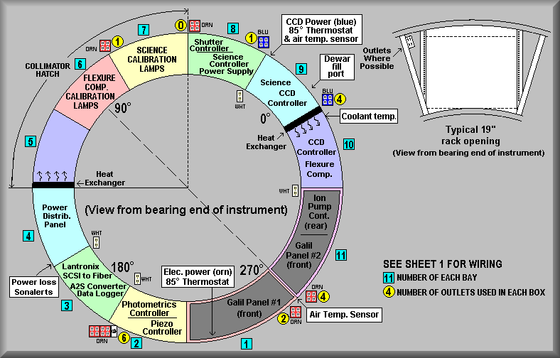
Electronics
Ring Equipment Locations |
| Bay Number: |
|
Equipment |
| |
|
Front |
Back |
| 1 |
|
Galil controller #1 |
Calibration lamp interlock box |
| 2 |
|
Photometrics TV camera controller
Tent Mirror Piezo actuator controller |
N/A |
| 3 |
|
Lantronix Terminal Server
SCSI-to-Fiber Convertor
AIA-to-SCSI Convertor
HP Datalogger - Temeratures |
N/A |
| 4 |
|
AC Power distribution panel |
N/A |
| 5 |
|
Empty |
N/A |
| 6 |
|
Flexure Compensation System lamps |
N/A |
| 7 |
|
Calibration lamp power supplies |
N/A |
| 8 |
|
Science CCD controller power supply |
Shutter controller |
| 9 |
|
Science CCD controller |
N/A |
| 10 |
|
FCS CCD controller |
N/A |
| 11 |
|
Galil controller #2 |
Ion Pump controllers |
Troubleshooting:
The controller also connects to the servo amplifiers via four flat ribbon cables
each. These carry the signals between the controller and the amplifiers. The
cables carry the motor control and enable signals plus limit switch and miscellaneous
signals. To aid in troubleshooting, we have added extra ribbon cable connectors
to the cables that allow a technician to probe the individual signal lines with
a meter or oscilloscope.
The following table contains links to pinouts for the ribbon cables that connect
the DMC-1580 controller to the Amp-1140 amplifiers. The Jn and JDn
cables do not always carry the same signal on the same pins. The is mostly,
but not exclusively, true on J5 and JD5, the I/O cable. The last three cables,
the Galil I/O cables J1 - J3, are the cables that connect from the Galil 72-bit
I/O board to the Opto-22 relay racks.
Galil controller interconnect cable pinouts