Compressible Thermonuclear Flames with the FLASH Code
Introduction:
Current models of Type Ia supernova favor the explosion beginning
with a flame near the center of a white dwarf that accelerates as it
moves outward due to various instabilities (Landau-Darrieus, Rayleigh
Taylor). It is not known whether the burning front remains a subsonic
flame, or if at some point, a detonation forms. The mechanism for a
deflagration-detonation transition is not known, although several
candidate models exist.
A flame propagates by balancing thermal diffusion and nuclear
burning. Heat diffuses from hot ash to the cold fuel ahead of the
burning front, raising its temperature to ignition. The width and
speed of the burning front will depend on how rapidly energy is
released from nuclear burning, and how efficiently conduction can
transport energy to the material ahead of the front. For a typical
white dwarf central density of 2 x 10⁹ g
cm-3 and a pure carbon environment, the flame thickness is
3.74 x 10⁻⁵ and the speed is 191 km/s (Timmes and
Woosley 1992, hereafter TW). The radius of a white dwarf is ~
1 x 108 cm, meaning a full simulation of a
supernova will need to span 13 orders of magnitude spatially. As a
first step in understanding Type Ia supernova mechanisms, we have
begun to examine fully resolved thermonuclear flames using the FLASH
code, and restrict ourselves to physics on the microscopic scales.
Numerical Method:
The FLASH code incorporates compressible hydrodynamics (using PPM),
adaptive mesh refinement, a realistic equation of state
(electron-positron, ions, and radiation), and a nucle ar burning
module. To simulate a flame using the FLASH code, it was extended to
incorporate energy transport. In the diffusion approximation, thermal
transport can be expressed as a conductive heat flux:
q = -sÑT
where
s is the conductivity.
This heat flux is coupled to the hydrodynamics in the energy equation:
|
|
¶rE
¶t
|
+ Ñ·(
rE + P)
|
®
v
|
= r
|
®
v
|
·
|
®
g
|
-Ñ·q
|
|
In FLASH, this is accomplished by using operator splitting. The
diffusion timescale is
where cv is the specific heat at constant volume / mass,
and dx is the zone width. At the length
scales necessary to resolve a flame (typically 10-5 cm to
.1 cm), the diffusion timescale is typically several orders of
magnitude larger than the CFL timescale, allowing us to use an
explicit method for the conduction.
In FLASH, conduction is treated as a separate module. The heat
flux is computed and added directly to the energy flux returned by the
Riemann solver. These fluxes are then used to advance the cell
average variables to the new time. Treating the heat flux this way
ensures that the code remains conservative: whatever heat flux is
added to one zone is subtracted from its neighbor.
To compute the heat flux, we use a conductivity module that treats
the physics of white dwarf interiors (Timmes 1999), including the
effects of electron-ion scattering, electron-electron interactions,
and electron-phonon interactions in the degenerate regime. These
conductivities are expressed as an equivalent opacity, and along with
radiative opacities, are combined to form the total conductivity:
|
s =
|
4 a c T3
3
r
|
|
æ
ç
è
|
1
kcond
|
+
|
1
krad
|
ö
÷
ø
|
|
|
This module is called on a directly by the conduction module.
Other conductivity routines, representing different physics can easily
be substituted in place of the current one.
1-dimensional Carbon Flames:
The first test of these modules is reproducing the known
1-dimensional laminar flame speeds for white dwarf interiors. A table
of these, used as a benchmark, was presented in TW. Here we consider
only the pure carbon environments.

| |
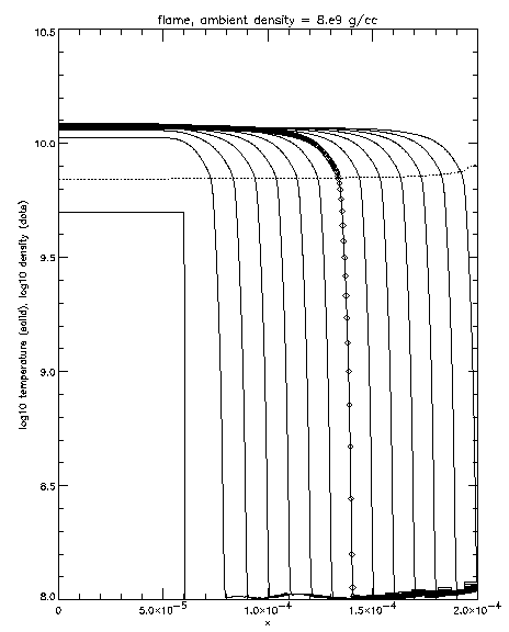
Fig. 1: Pure Carbon Flame Evolution, r = 8 x 10⁹ g
cm-3. Solid lines show the temperature at
different times, spaced 2 x 10-13 s
apart. The grid spacing for this calculation was
3.9 x 10⁻⁷ cm, at the finest resolution,
putting approximately 18 zones in a flame width. Diamonds on
one temperature curve show the zones. The dotted line shows
the density corresponding to the last temperature curve.
|
|
To start the flame, the temperature in a small region of uniform
density was raised to 5 x 10⁹ K, at which point
carbon burning will proceed rapidly. This sends out a pressure wave
which quickly leaves the domain, leaving behind a hot region of ash.
The energy released from the burning diffuses into the cold material
ahead of the front, raising its temperature to ignition. This quickly
enters a steady state, and a laminar flame front is formed. Figure 1
shows a flame front in a density of 8 x 10⁹ g
cm-3.

| |
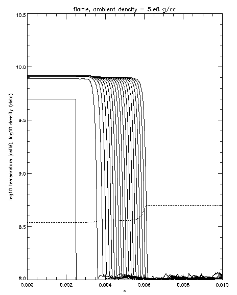
Fig. 2: Pure Carbon Flame Evolution, r = 5 x 10⁸ g
cm-3. Solid lines show the temperature at
different times, spaced 2 x 10-11 s
apart. The grid spacing for this calculation was
9.8 x 10⁻⁶ cm, at the finest resolution,
putting approximately 39 zones in a flame width. The dotted
line shows the density corresponding to the last temperature
curve.
|
|
At this high density, we see the flame front is very steep and
quickly moves across the domain. Note that the density falls behind
the flame front. Figure 2 shows a flame front in a medium of density
5 x 10⁸ g cm-3. Note that the domain
is almost two orders of magnitude larger to accommodate the larger
flame width. The density drop behind the front is larger for the low
density case.
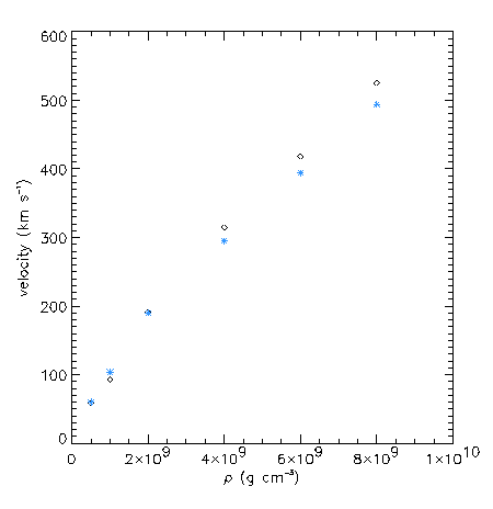
This comparison was done for many densities and the flame speeds
were compared to those tabulated in TW. The comparison appears in
figure 3.

| |
Fig. 3: Comparison of flame speeds produced in FLASH
(blue X) and those from TW (black diamonds)
|
|
In general, the results from FLASH agree very well with those in
TW. The largest difference in speeds is only 10%. Differences may be
partially explained by the slightly different physics used in the two
calculations. The TW results used a 130 isotope nuclear reaction
network, while FLASH currently employs a 13 isotope a-chain network. As demonstrated in TW, the flame
speed is sensitive to the nuclear reaction network size.
2-dimensional flames:
The thermal conduction module is extended to higher dimension via
dimensional splitting, in the same manner as the current
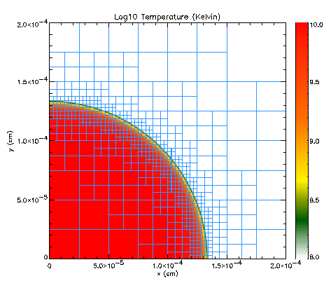
implementation of PPM. As a test of the diffusion in 2-dimensions, a
flame with an initially circular perturbation was simulated with
FLASH. After 10,000 timesteps, the burning front remained circular to
the resolution of the calculation (see figure 4). This problem also
illustrates the effectiveness of AMR at resolving the flame front.

| |
Fig. 4: 2-dimensional circular flame front showing AMR
refinement.
|
|
Go back to Astrophysics Group Gallery page
Go back to main Flash Gallery page
This file was last modified on 10 October 1999.
zingale@flash.uchicago.edu


