CAUTION: Text in RED is not correct!!
Miscellaneous Drawings
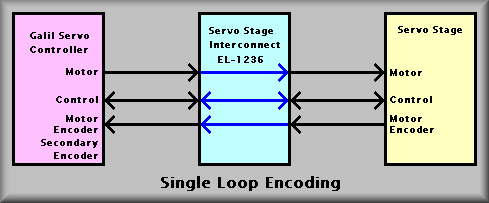
Stage Interconnect Box - Single Loop Encoding,
![]() EL-1236
EL-1236
Schematic: schematics/MULTIPURPOSE/Sloop.sch.pdf
Page last updated: May 14, 2002
Each servo motor stage has an interconnect box. It's used to provide a single location for the stage wiring to terminate. It also provides terminal strips to act as a break-out. The cover can be removed and a technician can then probe any of the signals going to or from the stage.
Single loop version is the simplest of the interconnect boxes. It simply passes all of the motor, encoder, and limit switch signals to and from the Galil controller and the stage.
The stages that use single loop encoding are:
Controller Axis #1 A TV Filters Stage
#1 B TV Focus Wheel Stage
#1 E CCD Focus
#1 F CCD Translation
#1 G Science Filter Wheel
#2 D Grating Slide
#2 E Slitmask Cassette
Sheet 1 shows the pin outs of the connectors and terminal strip in schematic form. Sheet 2 shows the physical layout of the various components and wiring of the box. Sheet 3 is a wiring list that specifies the connections within the box.
CAUTION: Text in RED is not correct!!
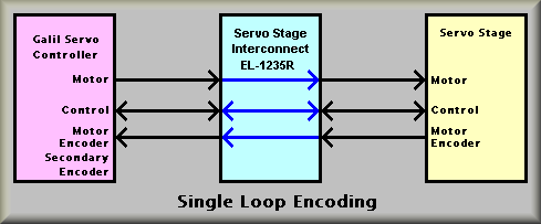
Stage Interconnection
Box - Single Loop Encoding, ![]() EL-1236R
EL-1236R
Schematic: schematics/MULTIPURPOSE/SloopR.sch.pdf
Page last updated: May 14, 2002
Each servo motor stage has an interconnect box. It's used to provide a single location for the stage wiring to terminate. It also provides terminal strips to act as a break-out. The cover can be removed and a technician can then probe any of the signals going to or from the stage. Because the mechanical design can have the motor mounted either of two ways, the electronics has to be able to interpret either clockwise or counterclockwise motor rotation as 'counting up' or 'counting down' on the encoder. This is accomplished by using a 'reverse phase' interconnect box. These boxes are designated with a "R" suffix, i.e. EL-1236R or EL-1272R. Because the input connector for the motor encoder is an IDC 10-pin connector, these boxes swap the A+ and A- signals for the B+ and B- signals inside the interconnect box. This enables the encoder to count up or down while the stage moves in the correct direction.
Generally, the motor leads must also be swapped. This is done where the motor leads are wired to the motor lead connector JB2. The change is made there instead of at the motor so that the red wire will still go to the red terminal and the black wire will still go to the black terminal of the motor. In some cases, the forward and reverse limit switch input must be changed also. Again, that is done in the connector that attaches to JB3 of the stage interconnect box. The connections are wired in the connectors so that the actual interconnect boxes remain wired exactly alike.
CAUTION: Text in RED is not correct!!
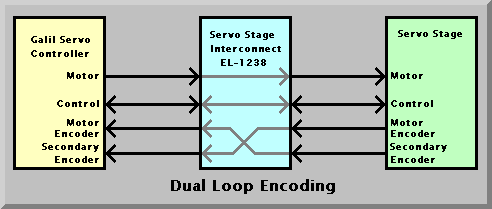
Stage Interconnection Box - Gurley Dual Loop
Encoding, ![]() EL-1272REV
EL-1272REV
Schematic: schematics/MULTIPURPOSE/SloopR.sch.pdf
Page last updated: May 14, 2002
Each servo motor stage has an interconnect box. It's used to provide a single location for the stage wiring to terminate. It also provides terminal strips to act as a break-out. The cover can be removed and a technician can then probe any of the signals going to or from the stage.
The dual loop version passes all of the motor, encoder, and limit switch signals plus the signals from a second encoder to and from the Galil controller and the stage. In this case however, the Secondary encoder is wired into the motor encoder inputs and the motor encoder is wired into the secondary encoder inputs. This allows the Galil controller to servo on the Gurley encoder instead of the motor encoder. Among other advantages, this means that the position information is coming directly from the stage position and not the motor encoder and thus does not see any 'sloop' in the drive system. Again, the second encoder requires the addition of two extra connectors: J4 is a DB-15 connector that cables to the Gurley encoder and J5 which cables back to the secondary encoder input connector of the amplifier panel.
The stages that use dual loop encoding are:
Controller Axis #2 A #2 B #2 C
CAUTION: Text in RED is not correct!!
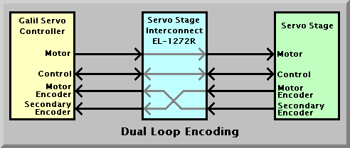
Stage Interconnect Box - Gurley Dual Loop
Encoding, ![]() EL-1272NORM
EL-1272NORM
Schematic: schematics/MULTIPURPOSE/Gur2loop_norm.sch.pdf
Page last updated: May 14, 2002
Each servo motor stage has an interconnect box. It's used to provide a single location for the stage wiring to terminate. It also provides terminal strips to act as a break-out. The cover can be removed and a technician can then probe any of the signals going to or from the stage. Because the mechanical design can have the motor mounted either of two ways, the electronics has to be able to interpret either clockwise or counterclockwise motor rotation as 'counting up' or 'counting down' on the encoder. This is accomplished by using a 'reverse phase' interconnect box. These boxes are designated with a "R" suffix, i.e. EL-1236R or EL-1272R. Because the input connector for the motor encoder is an IDC 10-pin connector, these boxes swap the A+ and A- signals for the B+ and B- signals inside the interconnect box. This enables the encoder to count up or down while the stage moves in the correct direction.
Generally, the motor leads must also be swapped. This is done where the motor leads are wired to the motor lead connector JB2. The change is made there instead of at the motor so that the red wire will still go to the red terminal and the black wire will still go to the black terminal of the motor. In some cases, the forward and reverse limit switch input must be changed also. Again, that is done in the connector that attaches to JB3 of the stage interconnect box. The connections are wired in the connectors so that the actual
The dual loop version passes all of the motor, encoder, and limit switch signals plus the signals from a second encoder to and from the Galil controller and the stage. In this case however, the Secondary encoder is wired into the motor encoder inputs and the motor encoder is wired into the secondary encoder inputs. This allows the Galil controller to servo on the Gurley encoder instead of the motor encoder. Among other advantages, this means that the position information is coming directly from the stage position and not the motor encoder and thus does not see any 'sloop' in the drive system. Again, the second encoder requires the addition of two extra connectors: J4 is a DB-15 connector that cables to the Gurley encoder and J5 which cables back to the secondary encoder input connector of the amplifier panel.
The stages that use dual loop encoding are:
Controller Axis #2 A #2 B #2 C