Cradle Wiring
The cradle stage wiring section of this manual contains descriptions of the rotation stage wiring and associated systems for the cradle portion of the DEIMOS Spectrograph. It corresponds to the Cradle Stage Wiring tab in the electronics schematics binder.
Rotation Renishaw Encoders, ![]() EL-3121
EL-3121
Schematic: schematics\ROTCOD.sch.pdf
Page last updated: February 18, 2003
Simplified Drawing
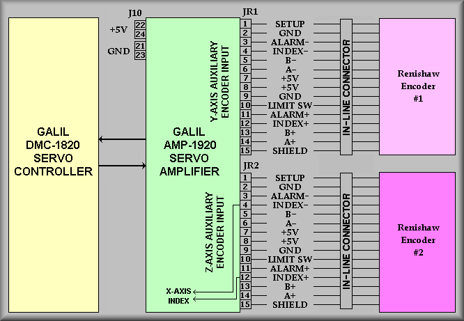
The above drawing shows the scheme used to bring the two Renishaw
encoder signal sets into the rotation PC. The Renishaws are mounted at the
rear bearing of the instrument to give two on-axis encoders. These encoders
are wired into the rotation computer via two DB15 connectors labeled JR1 and
JR2. The length of the stock encoder cables is insufficient to reach all the
way from the rear bearing to the controller so two cables were cut to length
and added. The inline connections are made behind the CCD UPS in the B bay.
From the connectors, the individual signals are wired to the screw terminal
strip of the AMP-1920 amplifier board.
Renishaw #1 is located to the left side of the bearing (as viewed from rear
of the instrument) and is wired to the main Y-Axix input. Renishaw
#2 is located to the right side of the bearing and in wired to the main
Z-Axis input. Note, however, that the index pulse from Renishaw encoder #
2 is wired into the main X-Axis index input. The resolution of the Renishaw
encoder are 3,353,000 counts per revolution or 9,313 counts/degree. As with
most dual encoded stages, the position loop is closed on the secondary, or
in this case, the Renishaw encoders, and the velocity loop is closed on the
motor encoder. The reason for having two Renishaw encoders was to allow them
to trade off so that the opposite encoder is keeping the position information
when either one crosses the encoder tape gap during rotation of the instrument.