Air
& Coolant Monitoring, ![]() EL-3005
EL-3005
Schematic: schematics/AIRCOOL.sch.pdf
Page last updated: June 14, 2002
Barrel Electronics
The barrel electronics section of this manual contains descriptions of the barrel electronics for the DEIMOS Spectrograph. It corresponds to the Barrel Electronics tab in the electronics schematics binder.
Air
& Coolant Monitoring, ![]() EL-3005
EL-3005
Schematic: schematics/AIRCOOL.sch.pdf
Page last updated: June 14, 2002
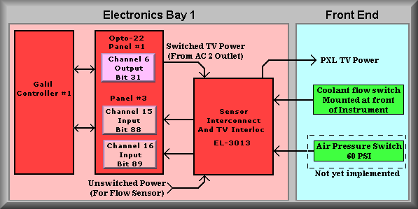
Simplified Drawing
The above drawing shows the first sheet of the two sheet air and coolant monitoring
drawing. The red block on the left represents Galil DMC-1580-72 controller #1.
It contains the software that monitors the coolant flow switch status. The second
red box contains the Opto-22 relay modules associated with the sensor wiring.
The top relay is and output used to turn on the PXL TV system. It is shown on
this drawing only because it connects to the TV interlock box. The middle block
represents input channel 15. It is the input bit for the Protheus flow switch.
This flow switch is mounted in the front of the instrument and monitors the
coolant flow in the guide TV camera system. The trip level is set to about 0.2
GPM. Below this level the switch will activate and signal to the TV Interconnect
box that the coolant flow is too low. The 'Normally Closed' contacts on the
flow meter are wired to control a mechanical relay in the interconnect box where
a set of contacts are used to pull the Opto-22 input module to ground. The lowest
block on the Opto-22 panel is an input that was designated for an air pressure
switch. The wiring for this sensor was not installed. As indicated by the different
background colors, the pink panel represents equipment in the electronics ring
'Bay 1' and the light blue panel represents equipment mounted at the front of
the instrument.